29 hits
Battery pack structure design, bending analysis, installation and fixation, and structural optimization
Abstract
As the sole power source of pure electric vehicles, the power battery pack bears the weight of battery modules and other components. Therefore, its strength and stiffness must meet operational requirements to ensure driving safety. Based on the establishment of its finite element model, this study analyzed the strength and stiffness of the battery pack structure under bending, emergency braking, high-speed turning, vertical extreme, and torsion conditions. The results showed that the stress on the battery pack bottom plate was the most severe under the vertical extreme condition. Thus, the original model was improved by changing the layout of the bottom plate reinforcing ribs. After simulating the same conditions, it was found that the overall mass was reduced while the mechanical performance was improved, achieving the goal of lightweight design.
Keywords: Power battery pack; Finite element method; Static analysis; Optimization design
Introduction
Small pure electric vehicles, as one of the strategic models for the industrialization of new energy vehicles in China, have attracted increasing attention. The power battery pack, as the sole power source of pure electric vehicles, plays a key role in ensuring the normal and safe operation of battery modules. This study conducts a static analysis on the battery pack structure of a domestic micro pure electric vehicle, calculates the stress and strain of the structure under external loads in different driving conditions, checks the strength and stiffness of the structure, identifies deficiencies in the original structure, and optimizes the design accordingly. This ensures improved performance of the battery pack while reducing its weight.
1. Battery Pack Structure Analysis
1.1 Finite Element Model of the Battery Pack Structure
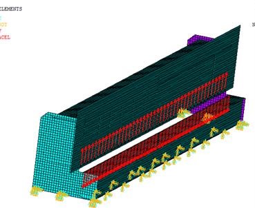
The battery pack is a box structure (as shown in Figure 1), welded from high-strength steel plates. Therefore, shell elements were used to simulate the battery pack structure. To reduce preprocessing workload without affecting overall calculation accuracy, the following simplifications were made when building the finite element model: ignoring small-sized chamfers, fillets, process holes, and other structures.
1.2 Boundary Condition Constraints
Boundary condition constraints are crucial in structural finite element analysis, as their correctness determines the accuracy of calculation results. Since the battery pack is connected to the vehicle body via 7 bolts, fixed constraints were applied to the connection parts.
1.3 Material Properties
The battery box bottom plate needs to bear large loads, so high-strength cold-rolled steel DC01 was selected. The material parameters are shown in Table 1.
Table 1 Material Parameters
Material Yield Strength (MPa) Tensile Strength (MPa) Density (g/cm³) Poisson's Ratio Elastic Modulus
DC01 210 270 7.85 0.30 2.07×10⁵
1.4 Calculation Conditions
Since this battery pack is used in a micro pure electric vehicle mainly operating on urban roads, five possible operating conditions during driving were analyzed: bending, braking, turning, vertical extreme, and torsion.
1.4.1 Bending Condition Analysis
The fully loaded static condition simulates the structural stress distribution and deformation when the electric vehicle is stationary or driving on smooth roads. Under this condition, the battery pack mainly bears the gravity generated by the mass of battery modules, control modules, and connecting components under gravitational acceleration.
1. Applied Loads
The battery pack is connected to the vehicle body via seven bolts, so it only needs to bear its own gravity (excluding the mass of passengers and cargo in the vehicle). The curb weight of the battery pack is 140kg, with gravitational acceleration g=9.8N/kg. Thus, the applied load is F=mg=140×9.8=1372N, applied at the center of gravity of the structure in the finite element model.
2. Analysis Results
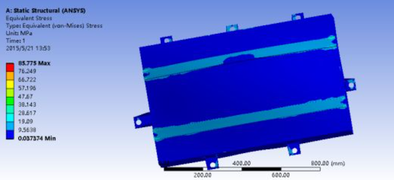
After calculation using ANSYS, the stress and strain nephograms of the battery pack structure were obtained (Figure 1.1).
Figure 1.1 Stress nephogram of the battery pack under full-load bending condition
The data shows the maximum stress in the structure is 85.775MPa, concentrated at the edges of the lifting lugs and bottom support ribs. This is mainly due to the large size of the battery pack and the long span of the reinforcing ribs, especially at both ends. However, the maximum stress (85.775MPa) is far below the material's yield limit, indicating the structure is safe.
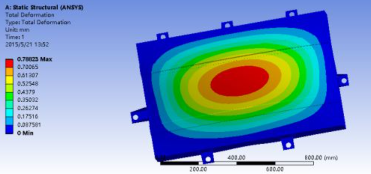
Figure 1.2 Strain nephogram of the battery pack under full-load bending condition
The strain nephogram shows the maximum deformation is 0.78823mm, occurring at the center of the load-bearing bottom plate. Although this deformation does not affect functionality, there is significant room for optimization.
1.4.2 Braking Condition Analysis
The high-speed braking condition simulates the load on the battery pack during emergency braking. During braking, the battery pack bears not only its own gravity but also inertial force caused by longitudinal braking acceleration. The inertial force depends on the braking acceleration and the battery pack's weight.
1. Applied Loads
The maximum braking acceleration was approximated using a=v²/2s (v = vehicle speed, s = braking distance under full pedal travel), measured as 0.8g=7.84m/s². Loads applied at the center of gravity include: gravity F1=mg=140×9.8=1372N, and inertial force F2=ma=140×0.8×9.8=1097.6N.
2. Analysis Results
The stress and strain nephograms under full-load high-speed braking are shown below.
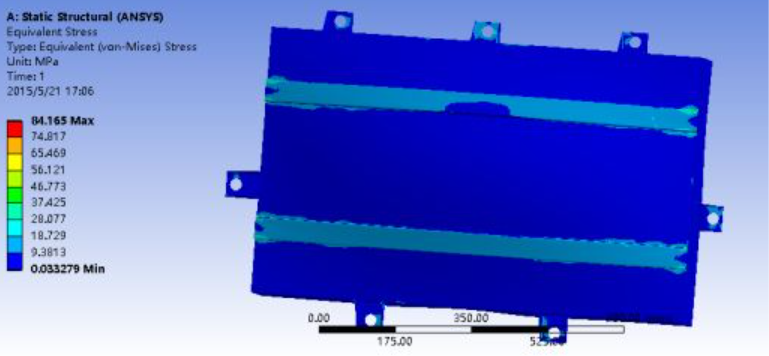
Figure 1.3 Stress nephogram of the battery pack under full-load braking condition
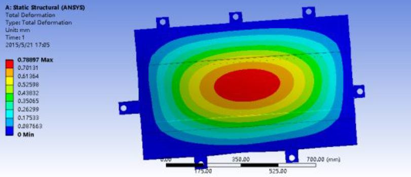
Figure 1.4 Strain nephogram of the battery pack under full-load braking condition
The maximum strain is 0.78897mm (center of the bottom plate), and the maximum stress is 84.165MPa (concentrated at the edges of the bottom support ribs and two lifting lugs in the X-direction). To analyze the local stress and strain of the lifting lugs, a separate finite element model was built, with meshing and independent load application: a -Z direction force of F=20×9.8=196N on the square boss surface of the lug, and a -X direction force of 156.8N on the cylindrical surface affected by braking inertia. Fixed constraints were set at 8 welding points (since lugs are spot-welded to the main structure).

Figure 1.5 Mesh of the lifting lug
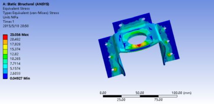
Figure 1.6 Stress nephogram of the lifting lug under braking condition
The maximum stress on the lug is 23.036MPa, concentrated at the lower welding points and the outer edge of the upper square boss (due to reduced material thickness). This is far below the yield limit, confirming structural safety.
1.4.3 Turning Condition Analysis
During high-speed turns, the vehicle body experiences lateral loads due to centrifugal force. Since the battery pack is connected to the body, it also bears lateral loads. Centrifugal acceleration depends on the turning radius and vehicle speed. Under this condition, the battery pack bears its own gravity and centrifugal force.
1. Applied Loads
For high-speed turning, a lateral acceleration of 0.5g was applied to simulate loads. The applied loads include: gravity F1=140×9.8=1372N, and leftward centrifugal force F2=140×0.5×9.8=686N.
2. Analysis Results
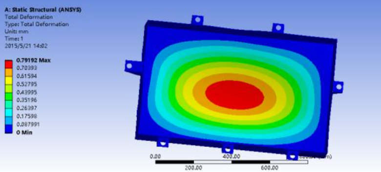
Figure 1.7 Strain nephogram under turning condition
The maximum strain (0.79192mm) occurs at the center of the battery-supporting floor, indicating the need for optimization in subsequent improvements.
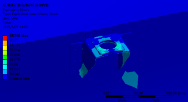
Figure 1.8 Stress nephogram of the lifting lug
Due to the leftward centrifugal force, the lifting lugs on both sides of the battery pack experience slightly higher tensile/compressive stress, with a maximum of 85.768MPa (still below the yield limit).
1.4.4 Vertical Extreme Condition Analysis
The vertical extreme condition simulates vertical jolt and resulting structural deformation when the vehicle travels on uneven roads .
1. Applied Loads
Under extreme conditions, the maximum vertical acceleration reaches 1g (in addition to gravitational acceleration), so the applied load is F=2mg=2×140×9.8=2744N.
2. Analysis Results
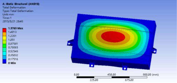
Figure 1.9 Strain nephogram under vertical extreme condition
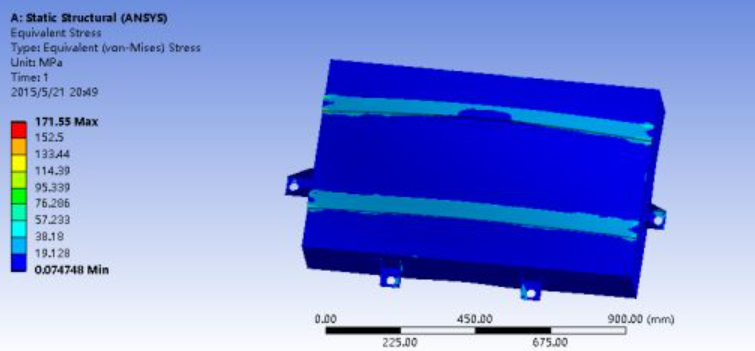
Figure 1.10 Stress nephogram under vertical extreme condition
Under 2g vertical load, the bottom deformation is significant, with maximum strain of 1.5765mm and maximum stress of 171.55MPa. Strengthening the center of the support bottom plate is therefore critical.
1.4.5 Torsion Condition Analysis
When the vehicle travels on uneven roads, one wheel may be lifted while the other is suspended. Asymmetric loading on both sides of the vehicle causes severe torsion of the battery pack. Insufficient torsional stiffness can lead to severe deformation, squeezing internal batteries and causing dangerous issues such as battery displacement, electrolyte leakage, or short circuits [3].
1. Applied Constraints and Loads
Asymmetric loads create torque, causing torsional deformation. A force difference of 1500N was applied between the two sides: 1500N on one side, and fixed constraints on the other. The side with two lifting lugs was fixed, while the side with three lugs had X and Y degrees of freedom restricted. The deflection of the loaded side was analyzed to determine torsional stiffness.
2. Analysis Results
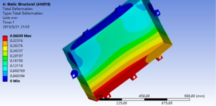
Figure 1.11 Strain nephogram under torsion condition
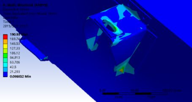
Figure 1.12 Stress nephogram of the 93mm-wide lifting lug under torsion condition
The maximum strain (0.36355mm) occurs on the loaded side, which is insufficient to cause battery displacement, indicating adequate torsional stiffness. The maximum stress is 190.95MPa, concentrated on the 93mm-wide lifting lug.
2. Optimization Design of the Battery Pack Structure
2.1 Summary of Structural Issues
Comprehensive static analysis revealed two common problems:
1. Stress concentration at the edges of the bottom support ribs under all four conditions.
2. Large deformation at the center of the bottom support plate.
2.2 Improvement Plan
1. The first issue arises from the large transverse size (1000mm) of the battery pack, leading to long spans of bottom support ribs and complex stress at edges due to heavy central loads. Thus, the bottom ribs were reoriented (perpendicular to the original direction) and increased from 2 to 3.
2. The second issue stems from large spacing between ribs, providing weak support to the central bottom plate. A rib was added at the center, with the other two ribs 218mm from the center, to enhance support and reduce deformation.
The modified 3D model is shown below:
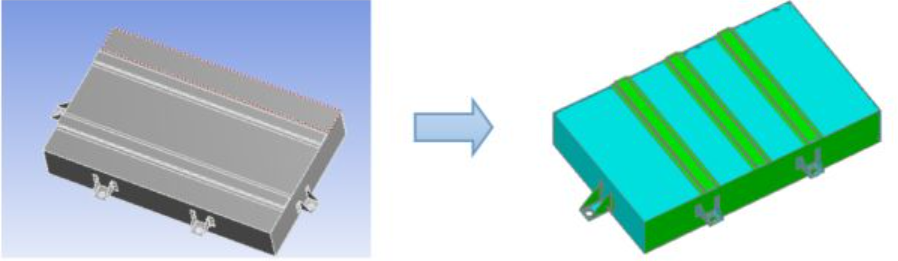
Figure 2.1 Schematic of the battery pack model before and after improvement
2.3 Verification of the Optimized Model
The new model was imported into ANSYS, and the same five conditions were simulated to analyze stress and strain. Changes in maximum stress and strain before and after optimization are compared in the bar charts below.
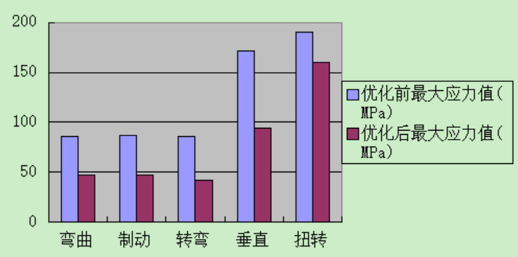
Figure 2.2 Bar chart comparing stress under various conditions before and after improvement
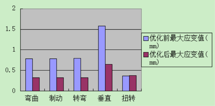
Figure 2.3 Bar chart comparing strain under various conditions before and after improvement
The comparison shows significant performance improvements: maximum stress decreased substantially under all conditions, and strain decreased by ~58% (except for a slight increase under torsion). Notably, the total length of reinforcing ribs reduced from 2000mm to 1836mm, reducing material usage by 164mm (with unchanged cross-section) and achieving lightweight design while improving performance.
3. Conclusion
This study established a finite element model of the power battery pack for a pure electric vehicle and conducted static analysis under different conditions to obtain stress and strain data. Common issues were summarized, and an optimization scheme was proposed. Verification via ANSYS showed the improved model had reduced maximum stress and strain (with a maximum stress reduction of 58.57%) and reduced material usage while maintaining performance. Thus, the optimization of the battery pack structure was successful.
Contact:
Prof. Tian:WhatsApp:+86 15029941570 | Mailbox:540673737@qq.com
we specialize in CAE finite element calculation and simulation, virtual prototyping and simulation testing, and product design optimization for enterprises and institutions.

Copyright © 2025.Boye Engineering Technology All rights reserved. Yue ICP17017756Num-1