22 hits
Mechanical Engineering
The Finite Element Method (FEM) is an engineering analysis technique based on numerical computation. It is widely applied in the field of mechanical engineering to solve complex problems involving structures, thermodynamics, dynamics, and more.
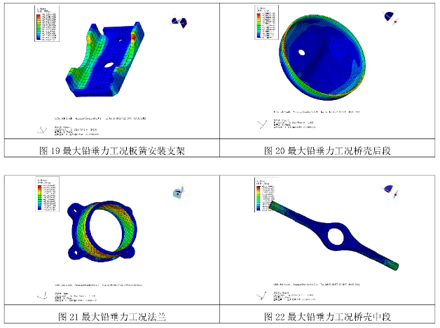
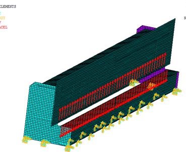
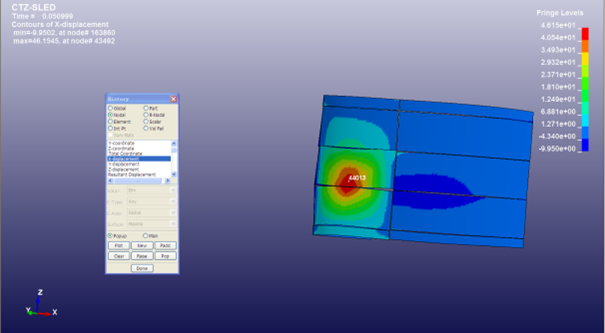
1. Structural Strength and Stiffness Analysis (See Figure 1)
Application Scenarios:
Stress and Deformation Calculation: Analyze stress distribution and deformation of mechanical components (e.g., shafts, gears, connecting rods) or entire structures (e.g., bridges, aircraft fuselages) under load.
Safety Assessment: Evaluate whether the design meets safety requirements by comparing the maximum stress with the material's yield strength.
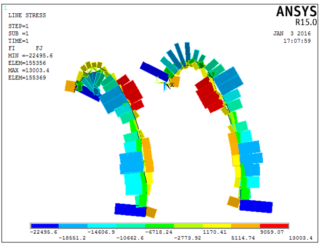
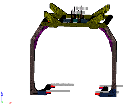
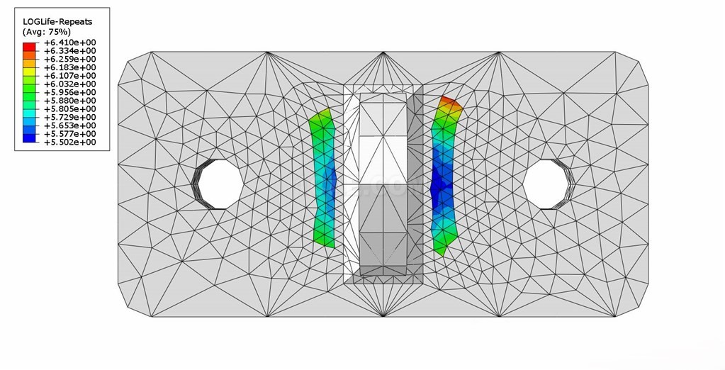
2. Fatigue and Life Prediction (See Figure 2)
Application Scenarios:
Cyclic Load Analysis: Simulate damage accumulation in mechanical components (e.g., engine crankshafts, bolts) under repeated loading, predicting fatigue crack initiation locations and service life.
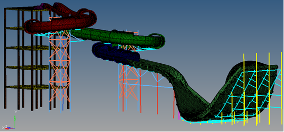
3. Vibration and Dynamic Analysis (See Figure 3)
Application Scenarios:
Modal Analysis: Calculate a structure's natural frequencies and mode shapes to avoid resonance (e.g., machine tool spindles, turbine rotors).
Harmonic Response Analysis: Analyze a structure's dynamic response under periodic loads (e.g., motor vibration).
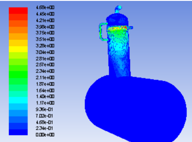
4. Thermodynamics and Thermal Stress Analysis (See Figure 4)
Application Scenarios:
Temperature Field Simulation: Predict temperature distribution in equipment (e.g., engine blocks, electronic chips) under thermal loads.
Thermal Deformation and Stress: Analyze thermal expansion/contraction and resulting stresses caused by temperature gradients (e.g., welding distortion, brake disc thermal stress).
5. Contact and Friction Analysis
Application Scenarios:
Contact Stress Calculation: Analyze contact pressure distribution at interfaces like gear meshing or between bearing rollers and races.
Friction and Wear Prediction: Optimize surface treatment processes to reduce wear (e.g., piston rings and cylinder walls).
6. Design Optimization
Application Scenarios:
Topology Optimization: Achieve lightweight design through optimized material distribution (e.g., aircraft trusses, automotive frames).
Shape Optimization: Adjust geometric shapes to reduce stress concentrations (e.g., fillet design at transitions).
7. Manufacturing Process Simulation
Application Scenarios:
Forming Process Analysis: Predict defects in processes like casting, forging, and injection molding (e.g., shrinkage porosity, springback).
Residual Stress Prediction: Assess residual stress distribution after processes like welding or heat treatment.
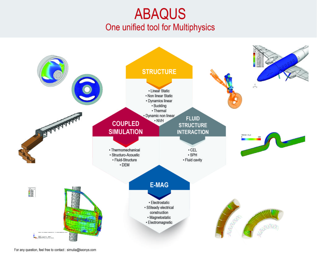
8. Multi-Physics Coupling Analysis
Application Scenarios:
Fluid-Structure Interaction (FSI): Analyze interaction between fluids and structures (e.g., aeroelasticity of wind turbine blades).
Thermal-Structural Coupling: Study the mutual influence of temperature fields and mechanical fields (e.g., thermal fade in braking systems).
9. Composite Materials and Nonlinear Material Analysis
Application Scenarios:
Anisotropic Materials: Analyze interlaminar failure in fiber-reinforced composites (e.g., carbon fiber car bodies).
Nonlinear Behavior: Simulate hyperelastic deformation of rubber seals or metal plastic forming.
10. Biomechanics and Medical Device Design
Application Scenarios:
Implant Mechanics Analysis: Optimize stress distribution in artificial joints (e.g., hip prostheses).
Biological Tissue Simulation: Study the response of bones and muscles under load.
Core Advantages of the Finite Element Method
Simplification of Complex Problems: Discretizes a continuum into finite elements, applicable to arbitrary geometries.
Cost and Time Savings: Reduces the number of physical tests, shortening product development cycles.
Multi-disciplinary Integration: Supports coupled simulation of multi-physics fields including structural, thermal, fluid, and electromagnetic.
High-Accuracy Prediction: Provides highly credible results by incorporating material nonlinearity and boundary condition nonlinearity.
Figure 1 Load-bearing capacity analysis of an automotive chassis
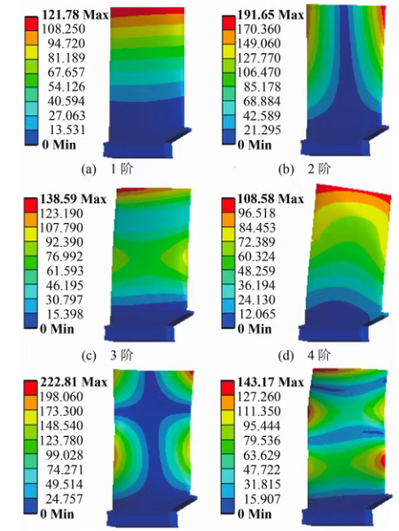
Figure 2 High-cycle fatigue analysis of an aero-engine blade
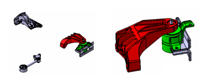
Figure 3 Vibration damping optimization of an automotive suspension system
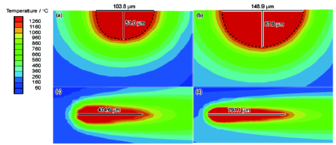
Figure 4 Heat-Affected Zone (HAZ) analysis during laser cutting
Contact:
Prof. Tian:WhatsApp:+86 15029941570 | Mailbox:540673737@qq.com
we specialize in CAE finite element calculation and simulation, virtual prototyping and simulation testing, and product design optimization for enterprises and institutions.

Copyright © 2025.Boye Engineering Technology All rights reserved. Yue ICP17017756Num-1