
9 hits
Structural Lightweighting,Fluid-Structure Interaction (FSI),Thermodynamics,Load Analysis,Life Prediction (especially Fatigue Life Prediction)
Aerospace
Finite Element Analysis (FEA) is a key technology in the aerospace field for design, verification, and optimization, covering the entire development process from overall aircraft performance to critical component details. Below are its core applications and typical cases:
1. Aircraft Structure and Lightweight Design (Fig. 1)
Application Scenarios: Fuselage stiffness analysis, composite material replacement (e.g., aluminum alloy → carbon fiber-reinforced composites), topology optimization (weight reduction while meeting aeroelastic stability).
Key Metrics:
Fuselage bending stiffness (Target typically > 50 kN·m/°)
Wing first-order flutter frequency (Avoid resonance with aerodynamic excitation, e.g., >15 Hz for commercial aircraft)
2. Aerodynamic Performance and Fluid-Structure Interaction (FSI) (Fig. 2)
Application Scenarios: Supersonic aerodynamic shape optimization, wing flutter suppression, thermal protection analysis at high Mach numbers.
Key Metrics:
Lift-to-drag ratio (Target >10, depending on flight phase)
Surface temperature gradient (e.g., <1500°C on hypersonic vehicle leading edges)
Toolchain: ANSYS Fluent, STAR-CCM+ coupled with FEA for flexible wing surface deformation analysis.
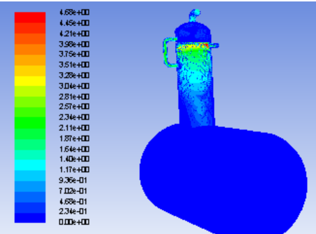
3. Propulsion System Thermodynamic Analysis (Fig. 3)
Application Scenarios: Turbine blade cooling channel optimization, combustion chamber thermal stress analysis, nozzle expansion efficiency simulation.
Key Metrics:
Turbine blade surface temperature (Nickel-based alloy temperature limit < 1200°C)
Combustion chamber pressure fluctuation (Target <5% of rated value)
Regulatory Requirements: Compliance with FAA Part 33 engine airworthiness certification.
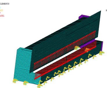
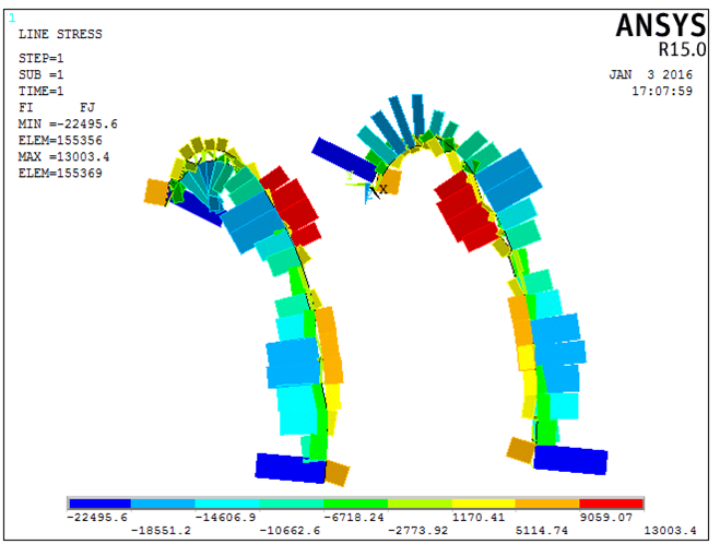
4. Spacecraft Structure and Launch Load Analysis (Fig. 4)
Application Scenarios: Rocket stage separation dynamics, satellite bracket vibration fatigue, re-entry capsule thermo-mechanical coupling simulation.
Key Metrics:
Maximum overload during launch phase (Typically <10g)
Ablative thickness of thermal protection layer (e.g., <30mm for return capsule)
Methodology: Transient dynamics analysis combined with heat transfer co-simulation.
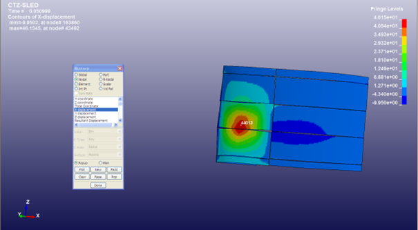
5. Damage Tolerance of Composite Structures (Fig. 5)
Application Scenarios: Laminate delamination prediction, impact damage assessment of honeycomb sandwich structures, repair solution validation.
Key Metrics:
Compression After Impact strength (CAI > 200 MPa)
Crack growth rate (Paris law parameter fitting)
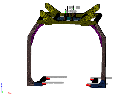
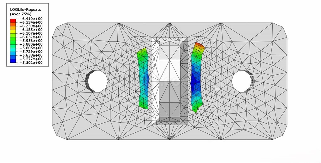
6. Fatigue and Life Prediction (Fig. 6)
Application Scenarios: Landing gear fatigue life assessment, fuselage skin cyclic load analysis, engine main shaft crack initiation prediction.
Load Input: Based on flight mission profiles (e.g., A380 typical mission cycle).
Tools: nCode, FE-SAFE combined with rainflow counting method.
Typical Software Tools
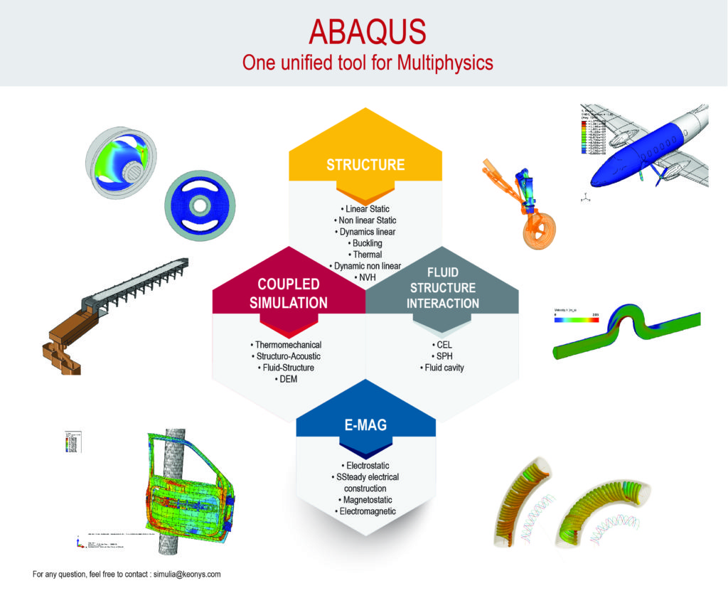
Structural Dynamics: NASTRAN, ABAQUS
Multiphysics Simulation: ANSYS Mechanical, COMSOL Multiphysics
Aerodynamic & Thermal Analysis: STAR-CCM+, CFX
Optimization Design: Altair OptiStruct, HEEDS
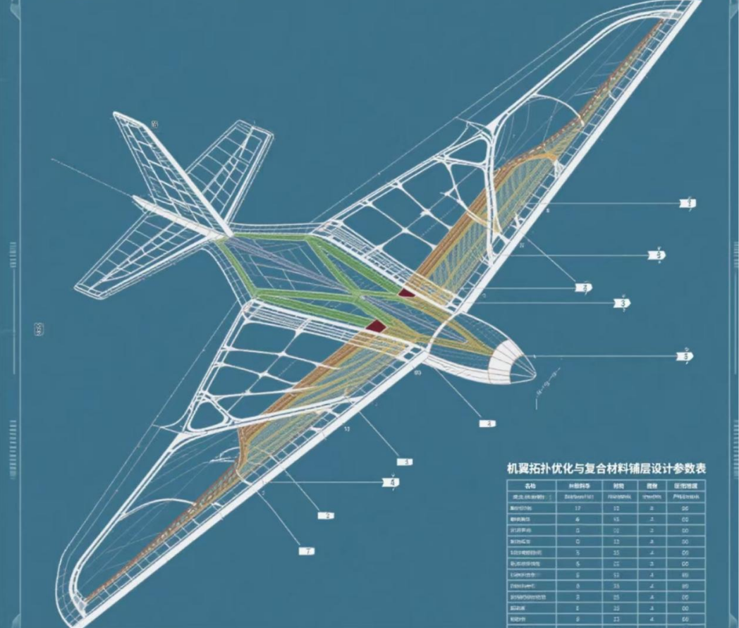
Figure 1: Wing Topology Optimization and Composite Laminate Design

Figure 2: Aerodynamic Heating Contour of a Hypersonic Vehicle
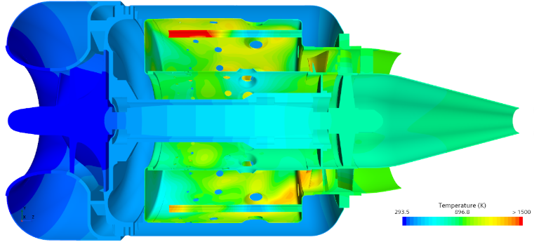
Figure 3: Turbine Blade Cooling Channel Temperature Distribution
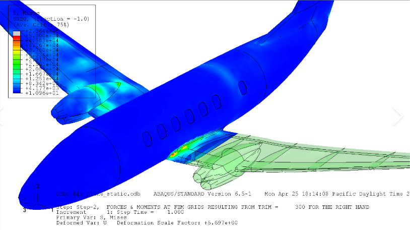
Figure 4: Stress Analysis During Aircraft Flight
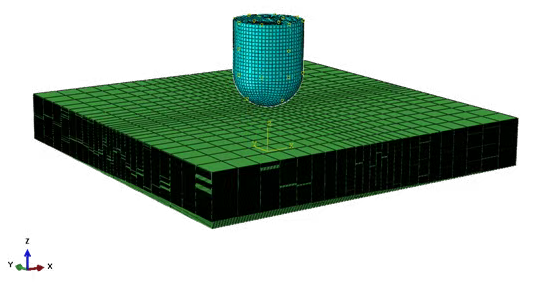
Figure 5: Composite Laminate Impact Damage Simulation
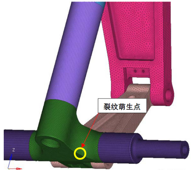
Figure 6: Landing Gear Fatigue Crack Growth Prediction
Contact:
Prof. Tian:WhatsApp:+86 15029941570 | Mailbox:540673737@qq.com
we specialize in CAE finite element calculation and simulation, virtual prototyping and simulation testing, and product design optimization for enterprises and institutions.

Copyright © 2025.Boye Engineering Technology All rights reserved. Yue ICP17017756Num-1