13 hits
Lightweight structure, impact resistance, durability, fluid-structure coupling
Finite Element Analysis (FEA) in the Automotive Industry
In the automotive industry, Finite Element Analysis (FEA) has become a core tool for design, validation, and optimization, covering the entire development process from vehicle performance to component details. Below are its key applications and typical cases in the automotive field:
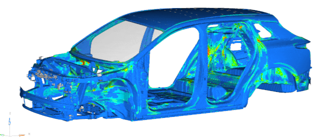
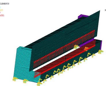
1. Body Structure and Lightweight Design (Figure 1)
Application scenarios: Body stiffness analysis, material substitution (e.g., steel → aluminum/carbon fiber), topology optimization (reducing weight while meeting collision standards).
Key indicators: Static torsional stiffness (typically target > 20 kN·m/°), modal frequency (to avoid resonance with road excitation, e.g., first-order modal frequency of passenger cars > 30Hz).
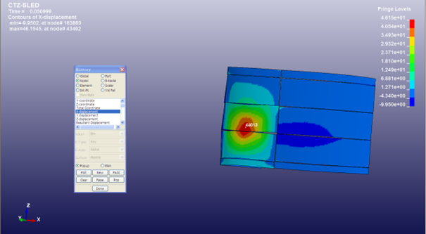
2. Crash Safety and Occupant Protection (Figure 2)
Regulatory requirements: Compliance with standards such as NCAP and FMVSS (e.g., frontal collision at 56km/h, side collision at 50km/h).
Role of FEA: Simulating airbag deployment timing, seatbelt load transmission, B-pillar intrusion (target < 150mm).
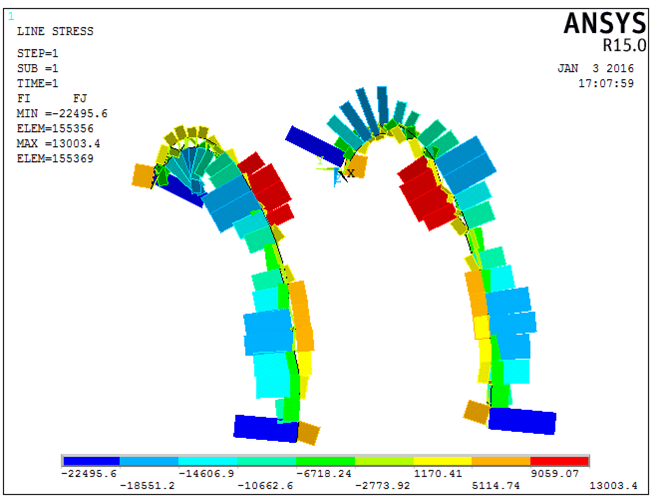
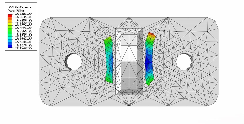
3. Chassis and Suspension System Durability (Figure 3)
Analysis type: Co-simulation of Multi-Body Dynamics (MBD) and FEA to predict fatigue life of components such as control arms and steering knuckles.
Load input: Based on measured road spectra (e.g., Belgian road conditions) or virtual roads (ISO 8608 standard).
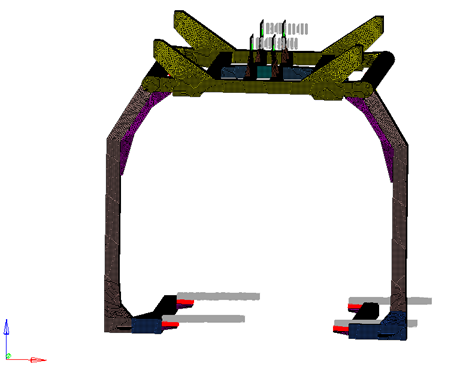
4. Powertrain NVH Optimization (Figure 4)
Problem scenarios: Engine vibration transmitted to the cabin (e.g., idle vibration < 0.3m/s²), gear whine noise.
- Methods: Modal superposition method to analyze structural transfer paths, optimizing bracket stiffness or adding damping materials.
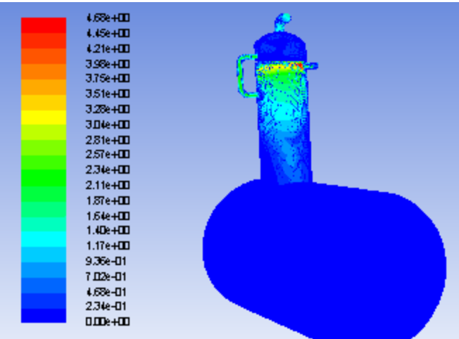
5. Battery Pack Structure and Thermal Management (New Energy Vehicles, Figure 5)
Mechanical safety: Simulating deformation of battery enclosures under extrusion/drop conditions (e.g., national standard GB 38031 requires no fire within 30 minutes). Thermal runaway simulation: Predicting thermal spread during cell thermal abuse (> 150℃), optimizing cold plate design.
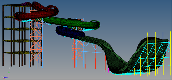
6. Aerodynamics and Fluid-Structure Interaction (Figure 6)
Applications: Reducing drag in external flow fields (target drag coefficient < 0.3), analyzing wind noise of wipers/rearview mirrors.
Toolchain: Star-CCM+ or Fluent coupled with FEA to analyze flexible components (e.g., sunroof flutter).
7. Intelligent Manufacturing and Process Simulation (Figure 7)
Stamping forming: Predicting springback of sheet metal parts (compensating die design with accuracy < 0.1mm).
Welding deformation: Optimizing BIW welding sequences (70% reduction in weld points after adopting integrated die casting).
Typical Software Tools
Crash/safety: LS-DYNA, PAM-CRASH
Fatigue analysis: nCode, FE-SAFE
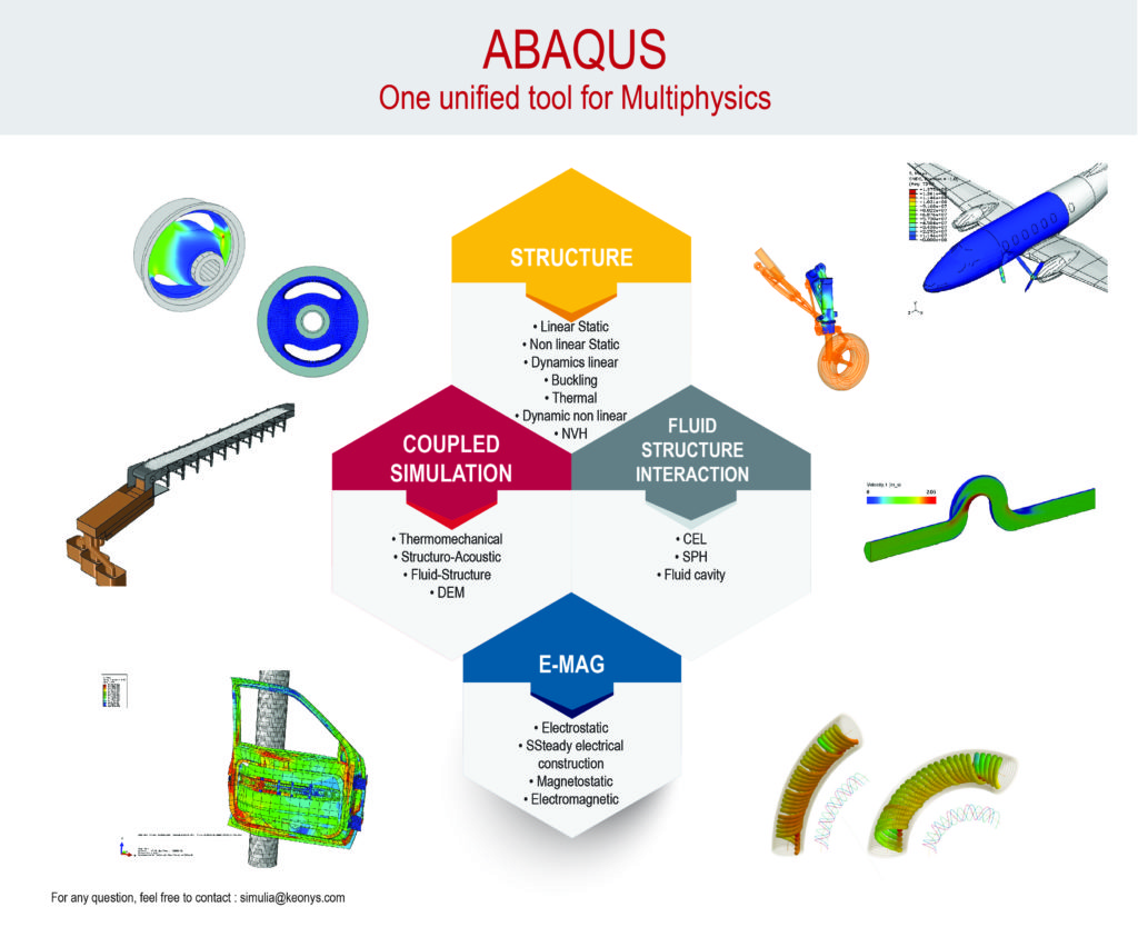
Multi-physics: ANSYS Workbench, COMSOL
Optimization design: OptiStruct, HEEDS
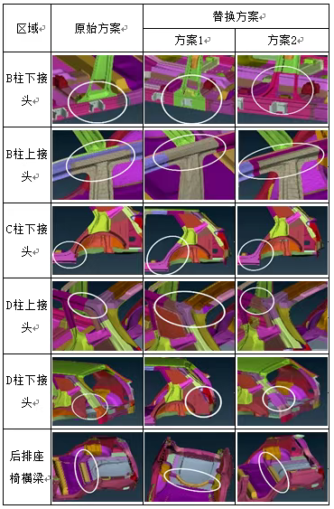
Figure 1: Structural optimization scheme for key body parts
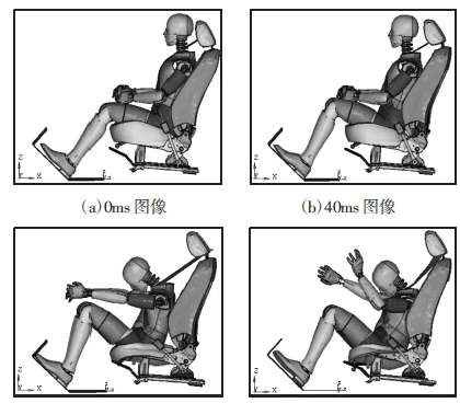
Figure 2: Frontal collision process of front seats
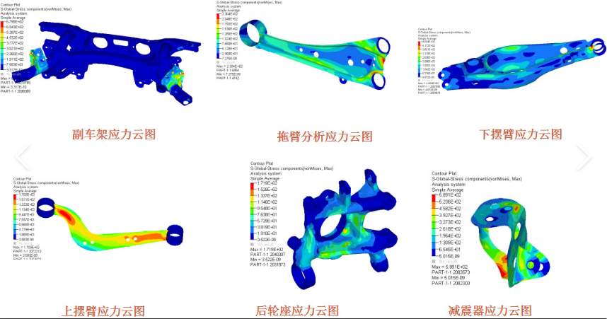
Figure 3: Stress cloud map of key chassis components
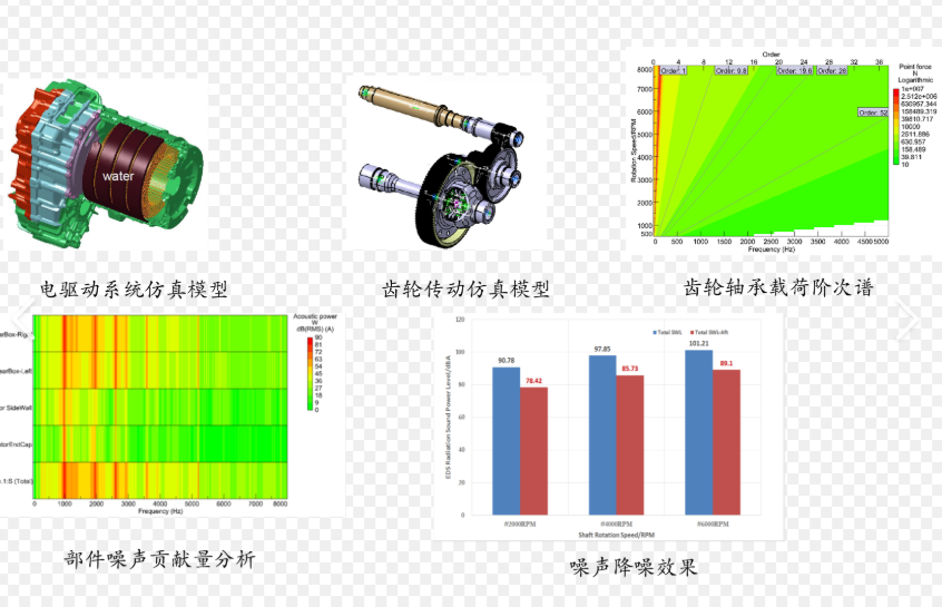
Figure 4: Powertrain NVH optimization

Figure 5: Battery pack structure and thermal management
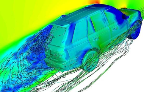
Figure 6: Automotive aerodynamics simulation analysis

Figure 7: Integrated die casting simulation results
Contact:
Prof. Tian:WhatsApp:+86 15029941570 | Mailbox:540673737@qq.com
we specialize in CAE finite element calculation and simulation, virtual prototyping and simulation testing, and product design optimization for enterprises and institutions.

Copyright © 2025.Boye Engineering Technology All rights reserved. Yue ICP17017756Num-1