18 hits
mesh generation
1. Software Introduction
Hypermesh software is a product of Altair Engineering (USA). It is a world-leading, powerful CAE application software package and an innovative, open, enterprise-level CAE platform. It integrates various tools required for design and analysis, offering unparalleled performance, high levels of openness and flexibility, and a user-friendly interface. Its most renowned feature is its powerful pre-processing capabilities for finite element mesh generation.
2. Finite Element Pre-processing
Hypermesh is used to complete the cleaning of the 3D geometric model and form the finite element model. According to the working conditions, it is shaped into a finite element model suitable for analysis, ensuring that the aspect ratio, included angles, distortion, etc., of the mesh elements are within reasonable limits for finite element calculation. The relationships between constraint/support conditions, geometric conditions, and loads are organized to create multi-case calculation files.
2.1 Finite Element Model Checking and Correction
Elements in the finite element model's stiffness matrix, mass matrix, and even damping matrix. This type of checking ensures model correctness by examining element warpage, distortion, maximum angle, minimum angle, aspect ratio (or squareness), and normal direction.
3. Mesh Inspection and Testing
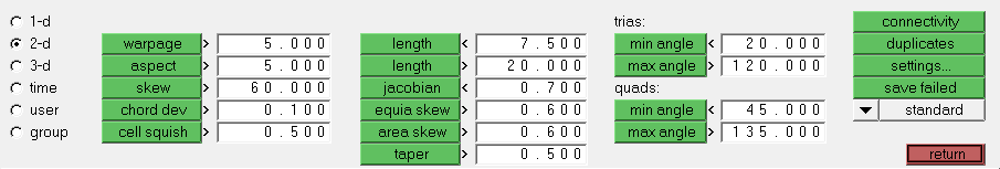
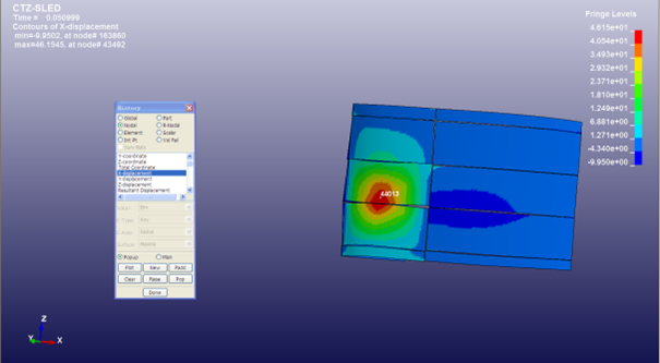
Mesh quality is related to the geometric characteristics of the specific problem and the solution algorithm. Therefore, mesh quality must ultimately be judged by the calculation results. However, experience shows that computational structural mechanics has some general requirements for meshes, such as aspect ratio, Jacobian, angles, warpage, etc. This solution applies a series of evaluation criteria within the Hypermesh pre-processing software to inspect mesh quality. Its inspection panel is shown in Figure 1:
Figure 1 HYPERMESH Mesh Inspection Control Panel
3.1 Warpage:
Warpage refers to the degree of in-plane bending of an element face. It checks the warpage amount of quadrilateral elements, i.e., the deviation of the element from a flat plane. Since 3 points define a plane, warpage occurs when one corner point of a quadrilateral is not coplanar with the other three. Generally, a warpage angle of less than 5° is acceptable. As shown in Figure 2, a larger angle indicates more severe warpage and poorer element quality. This solution specifies that warpage should not exceed 25 degrees.
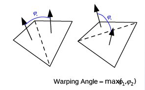
Figure 2 Element Warpage Evaluation Criteria
3.2 Aspect Ratio:
The dimensionless ratio of the maximum edge length to the minimum edge length of a mesh element. An aspect ratio of 1 represents the best element quality; the larger the aspect ratio, the worse the quality. For key structural feature areas, the aspect ratio must be strictly controlled within 5. See Figure 3.
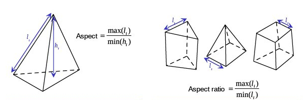
Figure 3 Element Aspect Ratio Evaluation Criteria
3.3 Jacobian:
Checks how much an element deviates from its ideal shape, quantified by the Jacobian value. The Jacobian value ranges from 0 to 1, where 1 represents the ideal shape. Hypermesh calculates the determinant of the Jacobian matrix at the Gaussian integration points or corner nodes of each element and outputs the ratio of the minimum to the maximum determinant, which is the Jacobian value. A ratio greater than 0.7 is generally considered acceptable. A ratio less than 0 indicates a concave element, which can cause convergence problems. 1 represents the best quality, 0 represents the worst quality. This solution specifies that this parameter should be greater than 0.3.
3.4 Angle:
Checks the maximum and minimum internal angles of each mesh element. The maximum internal angle should be less than 150 degrees, and the minimum internal angle should be greater than 30 degrees.
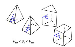
Figure 4 Element Angle Evaluation Criteria
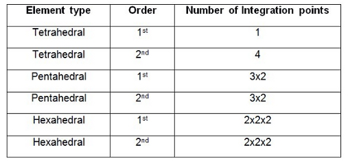
Figure 5 Internal Integration Points for Different Element Types and orders
Mesh Testing: Perform corresponding testing work on several sets of meshes that simultaneously satisfy the above mesh quality evaluation criteria. Too few mesh elements can cause insufficient resolution. Poor mesh quality can lead to increased numerical discretization errors. Preliminary trial calculations are necessary. If the calculation diverges after excluding other influencing factors, the cause may be a Jacobian value that is too low. High residuals in the continuity equation may be due to significant changes in scale between adjacent mesh elements.
Contact:
Prof. Tian:WhatsApp:+86 15029941570 | Mailbox:540673737@qq.com
we specialize in CAE finite element calculation and simulation, virtual prototyping and simulation testing, and product design optimization for enterprises and institutions.


Copyright © 2025.Boye Engineering Technology All rights reserved. Yue ICP17017756Num-1