1 hits
Key Applications and Case Studies of Solid Mechanics Analysis (CAE) in Mechanical Engineering
Solid mechanics analysis is a core technology in Computer-Aided Engineering (CAE), widely applied in mechanical design, material performance evaluation, and structural optimization. Below are its primary industrial applications and representative case studies:
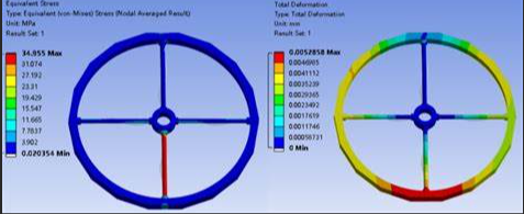
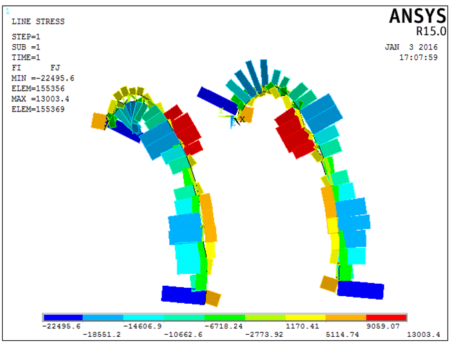
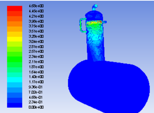
1. Static Strength Analysis of Mechanical Components (Fig. 1)
Applications:
Stress distribution in heavy-duty robotic arms,Strength validation of pressure vessels,Bending stress verification at gear tooth roots
Key Metrics:
Maximum equivalent stress (target < material yield strength, e.g., steel < 350 MPa)
Safety factor (typically > 1.5, per ASME standards)
Toolchain:
ANSYS Static Structural, ABAQUS Standard (with material nonlinearity models).
2. Dynamic Response & Vibration Analysis (Fig. 2)
Applications:
Resonance suppression in machine tool spindles
Random vibration analysis of automotive chassis
Modal analysis of wind turbine towers
Key Metrics:
First natural frequency (e.g., CNC spindle > 100 Hz to avoid machining excitation)
Peak vibration acceleration (target < 5g, per ISO 10816)
Methods:
Transient dynamics and harmonic response analysis using Lanczos eigenvalue solver.
3. Thermo-Mechanical Coupling Analysis (Fig. 3)
Applications:
Thermal stress evaluation in engine blocks
Heat dissipation optimization for electronics
Prediction of welding residual stresses
Key Metrics:
Equivalent thermal stress (e.g., aluminum components < 200 MPa)
Steady-state temperature uniformity (ΔT target < 50°C)
Tools:
COMSOL Multiphysics, ANSYS Mechanical (with heat transfer modules).
4. Nonlinear Contact & Friction Analysis (Fig. 4)
Applications:
Contact fatigue in bearing rollers/races
Bolt preload optimization
Compression-rebound simulation of seals
Key Metrics:
Contact pressure distribution (e.g., gear meshing zone < 1.2 GPa)
Frictional energy dissipation (target < 5% input power)
Methods:
Incremental step control + penalty method (supports large deformation).
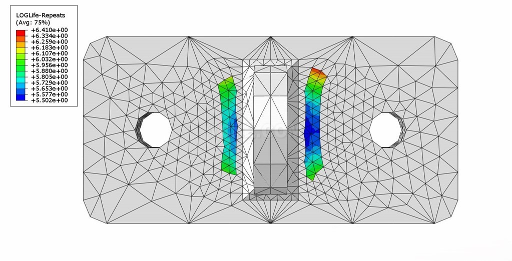
5. Fatigue Life & Damage Tolerance (Fig. 5)
Applications:
Cyclic load life prediction for high-speed train wheels
Crack propagation analysis in crane booms
Fatigue assessment of pipeline welds
Key Metrics:
Fatigue life (S-N curve based, target > 1e6 cycles)
Damage index (Miner’s rule < 1)
Tools:
FE-SAFE, nCode (local strain-life approach).
6. Composite & Additive Manufacturing Analysis (Fig. 6)
Applications:
Anisotropic strength validation of 3D-printed brackets
Buckling analysis of CFRP drive shafts
Crush failure simulation of honeycomb structures
Key Metrics:
Interlaminar shear strength (e.g., CFRP > 80 MPa)
Critical buckling load (target > 1.2× design load)
Standards:
ASTM D3039 (composite testing).
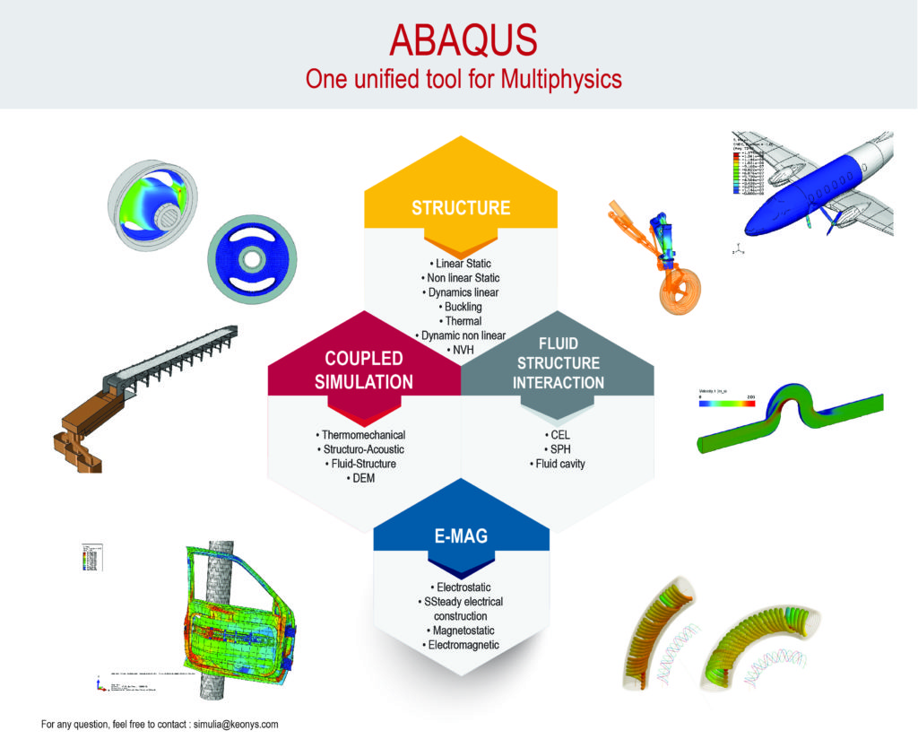
Typical CAE Software:
General Structural Analysis: ANSYS Mechanical, ABAQUS
Multiphysics Coupling: COMSOL Multiphysics, SIMULIA
Nonlinear Solvers: MSC Marc, LS-DYNA
Design Optimization: Altair HyperStudy, OptiStruct
Fig.1 Pressure vessel equivalent stress cloud diagram
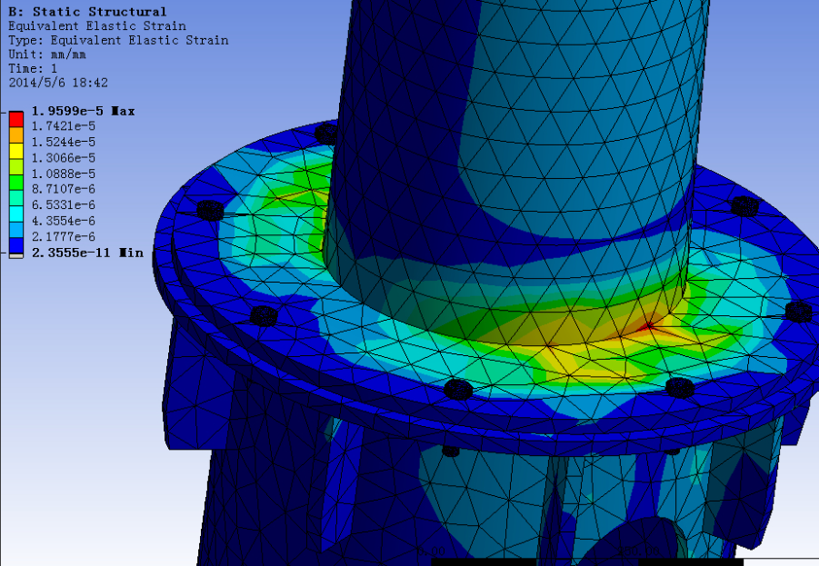
Fig.2 Modal mode of wind turbine tower
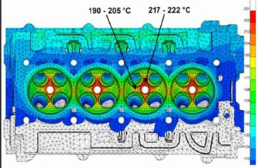
Fig.3 Distribution of engine cylinder temperature difference and thermal stress
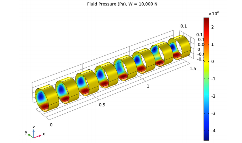
Fig.4 Bearing contact pressure and slip path

Fig.5 Distribution of fatigue damage of high-speed rail hubs
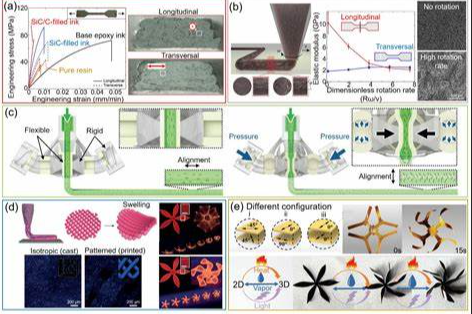
Fig.6 Anisotropic strain field of 3D printed bracket
Contact:
Prof. Tian:WhatsApp:+86 15029941570 | Mailbox:540673737@qq.com
we specialize in CAE finite element calculation and simulation, virtual prototyping and simulation testing, and product design optimization for enterprises and institutions.

Copyright © 2025.Boye Engineering Technology All rights reserved. Yue ICP17017756Num-1