ANSYS Structural Finite Element Analysis Process
The basic idea of the finite element method is to discretize a continuous structure into a finite number of elements, with a finite number of nodes defined within each element. The continuous body is treated as an assembly of elements connected only at nodes. Meanwhile, node values of the field function are selected as basic unknowns, and an approximate interpolation function is assumed within each element to describe the distribution of the field function in the element. Then, using variational principles in mechanics, finite element equations for solving node unknowns are established, converting an infinite-degree-of-freedom problem in a continuous domain into a finite-degree-of-freedom problem in a discrete domain. After solving, the field function in elements and the entire assembly can be determined using known node values and interpolation functions.
The goal of preprocessing is to establish a structural finite element model that conforms to actual conditions, performed in the Preprocessor module. It includes:
These tasks are implemented through the SOLUTION module:
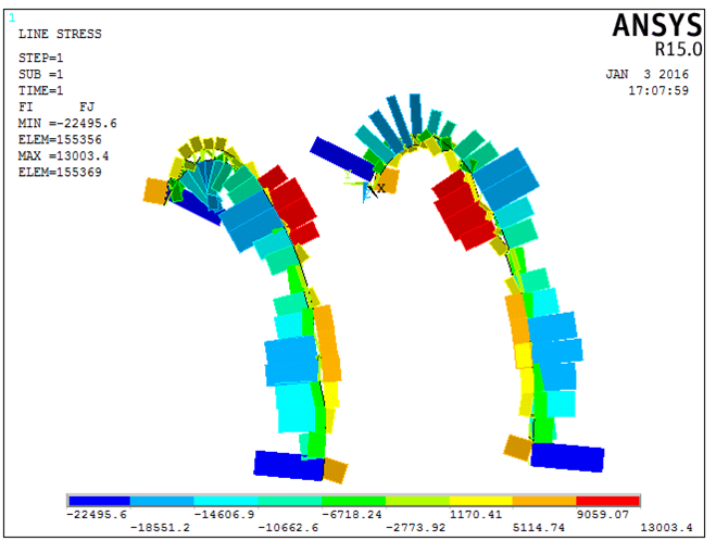
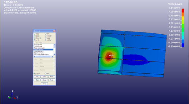
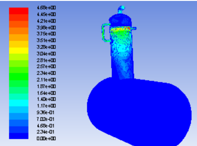
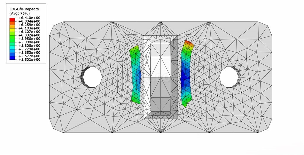
After completing the calculation, results are reviewed through postprocessing modules. ANSYS provides two postprocessing modules: the general postprocessor (POST1) and the time-history postprocessor (POST26). These modules enable easy access to solution results, including displacement, temperature, strain, and heat flux. Results can also be processed through mathematical operations and output in graphical or tabular form. Key outputs include structural deformation diagrams, internal force diagrams (axial force, bending moment, and shear force diagrams), node displacements, stresses, strains, and contour plots of displacement, stress, and strain—providing critical data for problem analysis.
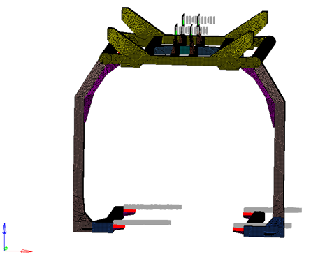
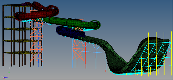
ANSYS offers over 100 element types to simulate various materials and structures in engineering. Combinations of different elements form abstract models for specific physical problems. For example:
Static analysis is generally required for structures, and results must meet design requirements. When dynamic loads are negligible compared to static loads, static analysis alone suffices. However, practical engineering structures may be subject to significant dynamic loads (e.g., buildings under earthquakes, ships under wave action, bridges under vehicle loads), requiring dynamic analysis. ANSYS dynamic analysis includes four types: modal analysis, harmonic response analysis, transient dynamic analysis, and spectrum analysis, addressing various engineering dynamic problems.
In ANSYS, modal analysis refers to the study of a structure’s natural vibration characteristics, focusing on natural frequencies and mode shapes. Its results serve as the basis for other dynamic analyses. Harmonic response analysis determines the steady-state response of linear structures under sinusoidally time-varying loads, revealing how structural response varies with frequency. Transient dynamic analysis calculates structural dynamic responses under arbitrarily time-varying loads, obtaining time-dependent displacement, strain, stress, and force under combined steady, transient, and harmonic loads. Spectrum analysis links modal analysis results with known spectra to calculate structural responses, used to determine dynamic responses to random or time-varying loads.
ANSYS also supports nonlinear analysis. Structural nonlinear problems fall into three categories: geometric nonlinearity, material nonlinearity, and state nonlinearity. Geometric nonlinearity arises from nonlinear strain-displacement relationships, leading to nonlinearity in the total stiffness equation of finite element analysis. Material nonlinearity stems from nonlinear material constitutive relationships, causing structural stiffness nonlinearity. State nonlinearity is associated with structural state changes, with contact problems being the most common example. For nonlinear analysis, in addition to general analysis options and load step settings, nonlinear options (particularly convergence criteria and equilibrium iteration counts) must be configured, which is critical for accurate results.
Contact:
Prof. Tian:WhatsApp:+86 15029941570 | Mailbox:540673737@qq.com
we specialize in CAE finite element calculation and simulation, virtual prototyping and simulation testing, and product design optimization for enterprises and institutions.

Copyright © 2025.Boye Engineering Technology All rights reserved. Yue ICP17017756Num-1