Analysis of road noise problem of a vehicle based on CAE technology
This paper addresses excessive noise at the driver’s right ear induced by road excitation during prototype testing of a domestic vehicle. By integrating experimental measurements with finite element technology, we used test data as excitation inputs for CAE-based transfer path analysis (TPA). Comparative validation with test results confirms the feasibility of CAE TPA. The root cause of the 53Hz peak identified in tests was successfully determined.
Keywords: Transfer Path Analysis (TPA), Road Excitation, Finite Element Method (FEM), Vibro-Acoustic Coupling
Introduction
With the rapid development of China’s automotive industry and increasing vehicle ownership, ride comfort has gained significant attention. Vibration and noise are critical factors influencing consumer purchasing decisions and serve as key metrics for vehicle quality assessment. To enhance market competitiveness, manufacturers prioritize NVH performance, often highlighting vibration and noise control as a selling point.
Road-induced vibration (predominantly <300Hz) is one of the three primary noise sources during driving, particularly pronounced on rough surfaces. Conventional solutions rely on experimental TPA to identify dominant noise paths for optimization. While frequency response functions (FRFs) and noise transfer functions (NTFs) are readily obtainable in classical TPA, accuracy is compromised by:
This study proposes a hybrid experimental-CAE TPA approach. Test-measured force spectra (60 km/h on asphalt) served as excitations for boundary element-based acoustic transfer vector analysis. CAE-calculated A-weighted SPL (1/3-octave, 20–200Hz) at the driver’s right ear was validated against test data. Subsequent CAE TPA evaluated vector contributions of each excitation path to pinpoint the root cause of road noise.
1. Analysis Theory
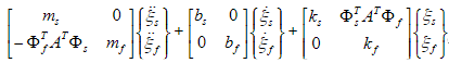
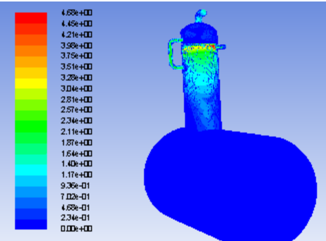
Road-tire interaction transmits vibration via the suspension to the body. Body panel vibrations generate noise that propagates through the cabin air, forming sound pressure at the driver’s right ear. Concurrently, air pressure constrains panel vibrations, creating vibro-acoustic coupling. Thus, analyzing sound pressure requires coupled structural-acoustic modal analysis, combining structural dynamics and fluid continuity equations:
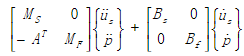
Subscripts:
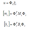
Structural modes (vacuum):
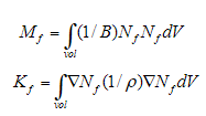
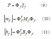
Fluid modes (rigid container):
Substituting Equations (2)–(12) into (1) yields the coupled system equation in modal coordinates:
2. Feasibility Verification
2.1 Test Data Acquisition
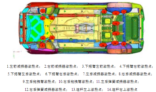
(1) Excitation Points:
Research confirms tire/road noise dominates at 50–60 km/h on dry surfaces, worsening on rough roads. Road excitation transfers to the body through two primary paths:
(2) Test Conditions:
(3) Data Collection:
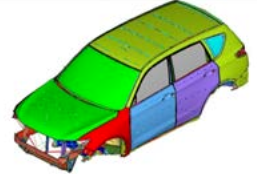
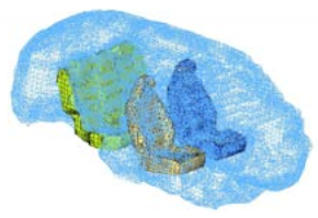
2.2 CAE Simulation
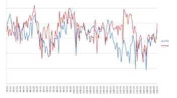
2.3 Test-CAE Correlation
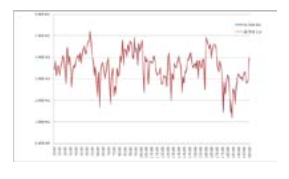
Driver’s right-ear sound pressure comparison (Fig. 4) confirms CAE accuracy, enabling path contribution analysis.
3. 53Hz Peak Noise Analysis
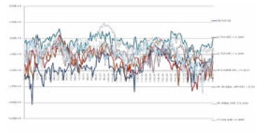
3.1 TPA Results
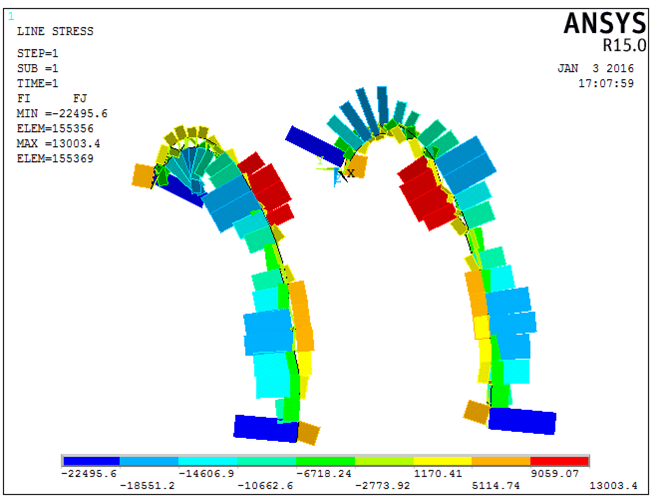
Dominant paths to 53Hz peak (Fig. 5):
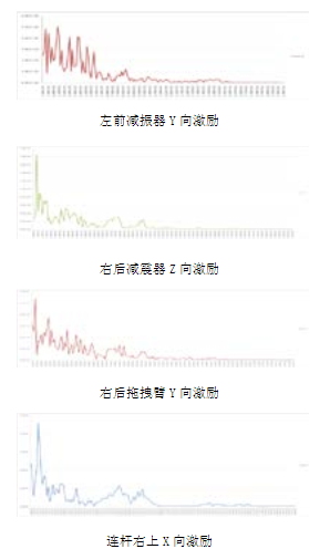
3.2 Excitation Source Analysis
All four paths show force spectrum peaks near 53Hz (Fig. 6).
To isolate cause:
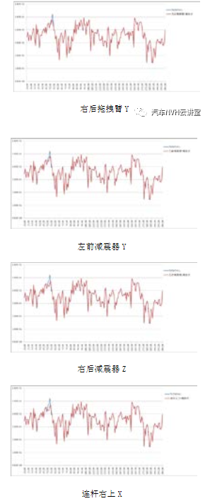
Conclusion: The 53Hz peak originated from road excitation spectra, not structural stiffness.
4. Conclusions & Outlook
Source: Proceedings of the 2016 International Symposium on Automotive NVH Control
Contact:
Prof. Tian:WhatsApp:+86 15029941570 | Mailbox:540673737@qq.com
we specialize in CAE finite element calculation and simulation, virtual prototyping and simulation testing, and product design optimization for enterprises and institutions.

Copyright © 2025.Boye Engineering Technology All rights reserved. Yue ICP17017756Num-1