Finite Element Analysis of Electro-Thermal Field in High-Speed Railway High-Power Traction Motors
Abstract
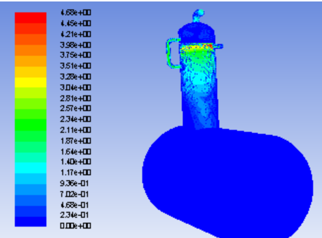
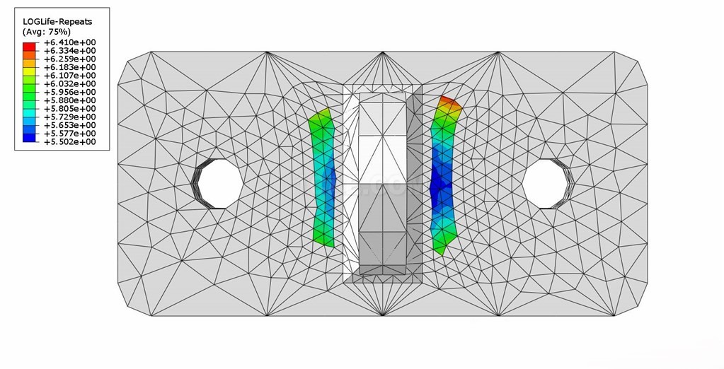
Aiming at the problems of excessive hot-spot temperature during operation and stator winding insulation failures caused by the high-powerization of traction motors, this study takes the MT205 high-power traction motor of CRH2 EMUs as the research object and establishes a three-dimensional finite element analysis model of the traction motor. Using the losses obtained from electromagnetic analysis as heat source excitation, this paper proposes to describe the air gap heat exchange capacity with effective thermal conductivity. With the Infolytica MotorSolve finite element analysis software, the global electromagnetic field and temperature field distributions of the stator and rotor of the traction motor under rated load are calculated. The analysis results show that the average temperature of the rotor area is 40°C higher than that of the stator, and the maximum temperature during motor operation reaches 166°C. The highest temperature is located at the junction of the outer surface of the rotor outlet side conductor bar and the rotor end ring. The stator winding temperature is significantly higher than that of the stator core, while the rotor squirrel cage bar temperature is slightly higher than that of the rotor core. The thermal stress in the middle of the stator core teeth is greater than that at the tooth top and yoke. The accuracy of the simulation results is verified by parametric analysis of the parameters affecting the stator temperature field and comparison with the temperature rise test results provided by the motor manufacturer during factory inspection.
1. Introduction
The rapid development of high-speed railways has put forward increasingly higher requirements for the capacity and operational reliability of traction motors. Restricted by the installation space of locomotives, the volume of traction motors is strictly limited, and their power density continues to increase. In addition, EMUs widely adopt AC drive PWM variable frequency speed control systems for traction control. Traction motors operate under a series of high-frequency, steep-rising edge square wave pulses, and high-frequency harmonics further increase internal motor losses. This leads to severe heating of various motor components, frequent over-limits of local hot-spot temperatures, and thus affects motor lifespan. When stator winding coils expand due to heat, insulation degradation and aging are accelerated. Relative displacement caused by thermal deformation between internal parts of conductors may even lead to insulation erosion. Currently, insulation failure is one of the three major frequent faults of traction motors (insulation, rotor bar breakage, and bearing). Therefore, accurately analyzing the temperature field distribution of traction motors, calculating hot-spot temperature rises and their locations, and optimizing the ventilation structure design of traction motors are important issues in the design and manufacturing of high-power traction motors.
Fully considering motor heat sources and accurately calculating heat dissipation coefficients of various components to determine temperature rises have become research hotspots among scholars at home and abroad. Due to the heterogeneous nature of motors, traditional methods in temperature field analysis mostly use equivalent thermal circuit methods to calculate average temperature rises, which fail to fully reflect specific temperature distributions and hot-spot locations. Some studies have considered the inhomogeneity of heat source distribution and established 2D temperature field models for the axial central section of motors using electromagnetic-thermal coupling methods but ignored axial temperature variations. Domestic scholars have conducted a series of studies on motor temperature field calculation, but insufficient consideration has been given to the inhomogeneity of heat source distribution. Only a few studies have calculated the 3D temperature field and thermal stress field of asynchronous motor rotors for rotor bar breakage faults.
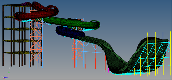
This paper adopts the finite element method, taking the MT205 high-power traction motor used in CRH2 EMUs as the research object. Based on the Infolytica MotorSolve finite element analysis software, a finite element model of the stator and rotor of the traction motor with an axial forced air-cooling structure is established. Heat transfer coefficients at various locations are obtained using empirical formulas. The electromagnetic field, steady-state temperature field distribution, and temperature rise curves of the stator and rotor under rated load are calculated. Finally, the validity of the model is verified by comparison with type test results.
2. Motor Electromagnetic Field Analysis
2.1 Finite Element Analysis Model of Traction Motor
Most EMU traction motors are powered by voltage-source inverters, which use PWM control technology and output voltages containing a large number of harmonics. Due to the axial symmetry of the motor's mechanical dimensions, a 2D finite element model of the traction motor is established. Table 1 shows the design parameters of the traction motor.
The following basic assumptions are made when analyzing the 2D electromagnetic field of the motor using the finite element method:
Leakage flux at the outer circle of the stator core and axial components of electromagnetic quantities are ignored in electromagnetic calculations;
The influence of temperature on electromagnetic parameters such as electrical conductivity and magnetic permeability is ignored;
The effect of rotating magnetic flux is not considered in iron loss calculation.
Contact:
Prof. Tian:WhatsApp:+86 15029941570 | Mailbox:540673737@qq.com
we specialize in CAE finite element calculation and simulation, virtual prototyping and simulation testing, and product design optimization for enterprises and institutions.


Copyright © 2025.Boye Engineering Technology All rights reserved. Yue ICP17017756Num-1